My Home Made Sinclairs
This webpage has some pictures and a brief description of the Sinclair computers I have so far built from scratch out of spare sinclair components.
The circuit boards and cases are all my own work, as well as the butchering of keyboards.
Click on the pictures to see a larger version.
ZX81
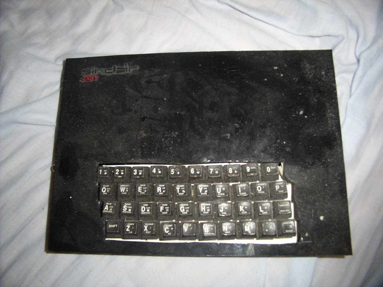
 The ZX81 was the first machine I built. The ULA I had to acquire from ebay, as the big box didn't have any of the elusive 2C210E ULAs. The 8K ROM, the 2114s that were replaced by the 16K upgrade (see below), the Z80 and the transistors all came from the box, along with the 7805 regulator, the ear/mic/DC in sockets, and the UHF modulator.
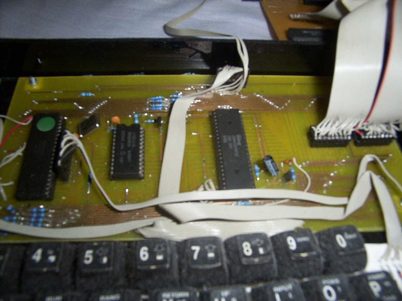
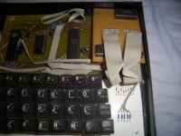
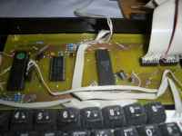 This is the digital board. The ULA is on the left, the 8K ROM is the small chip, and the CPU is to its right. On the far right are two smaller sockets that originally held 2114 1kx4 RAMs. 1K just wasn't good enough, and I built a 16K upgrade for it later on. You can see the ribbon cables for this upgrade dangling out.
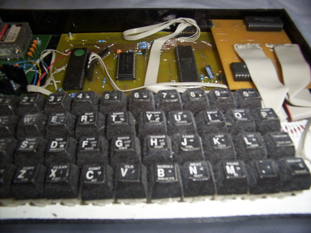
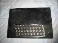
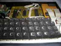 The keyboard was made using keyswitches from a BBC Micro keyboard (don't worry, the BBC micro was a dead unit). They were affixed to a slab of polythene sheet with connecting matrix wires soldered between them. The keytops are laser printed squares superglued on.
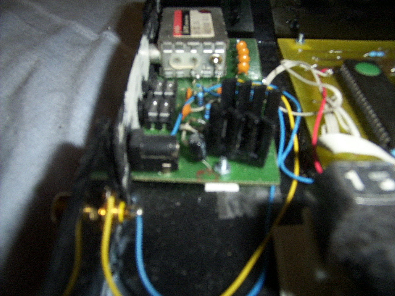
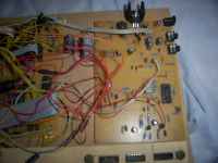
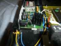 This is the analogue board, with the EAR and MIC sockets & circuitry, along with the UHF modulator and 7805 voltage regulator. Strangely enough, a sinclair "9V" PSU doesn't work correctly with this ZX81, but a 12VDC switch mode PSU does. Also visible is the composite video output for a cleaner signal.
 This is the 16K upgrade I built when 1K just wasn't enough (I also wanted to play Frogger). It is made of two 6264 ICs and a NOT gate connected to one of the upper address lines functions as a simplistic address decode for the 8Kx8 SRAMs. To save having to redesign the mainboard, I designed this to plug into the existing sockets with a flying lead to connect the remaining address lines.
ZX Spectrum 48K
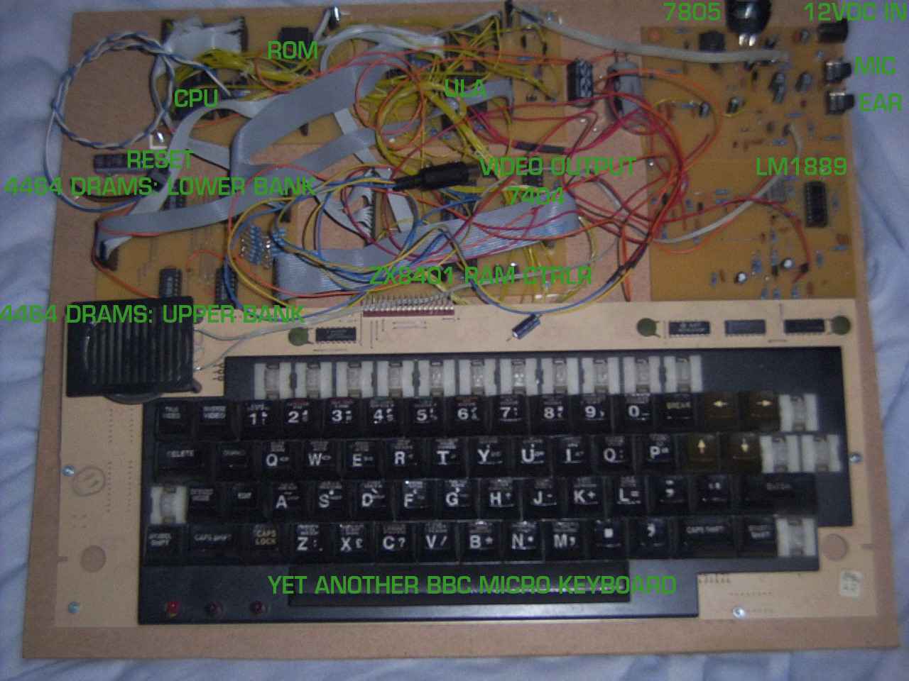
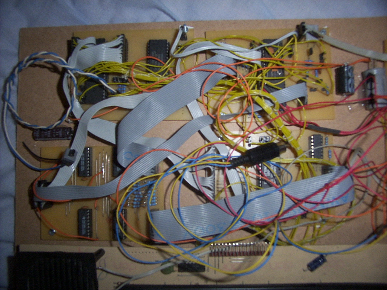
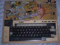 This is the ZX Spectrum I built after the success of the ZX81. I have not yet finished assembling the casing for it, so it still looks a little raw. Its quite hard to see the components under the mass of wires, so I have drawn guides on the full size version. The keyboard is yet another butchered BBC Micro keyboard, this time I left the keys on the board and simply cut the tracks and rewired the switches as required.
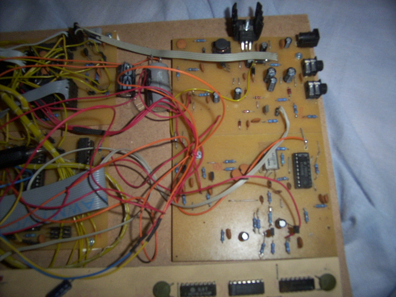
 As you can see, I built the digital part on 4 seperate boards: CPU & ROM, RAM, ULA, MEMORY CONTROLLER. The circuit conforms to the Issue 6a designs, but uses 4464 RAM chips (as I had these in abundance). By not using the 4116s, I've saved on the need for a -5V line. One consequence, was that it took a month before I discovered the 4464s had a different impendance to 4532s/4416s/4164s, meaning the data bus seperator resistors had to be upped from 470 ohms to 680 ohms. All works fine now.
 The analogue part was built on two further boards: The video section, and the Power & I/O section, the latter being near the top. The original design featured the great joke known as "The Sinclair Power Circuit" and tried to produce +12V and -5V along with +5V from the 7805 from a single 9V DC input. Something obviously wasn't right as my 12VDC was nearer 10V, and wasn't driving the 4116s correctly. I decided to scrap the 4116s and use 4464's instead, so most of the power circuit became redundant. This is also why the input is 12VDC and not 9V. The only part that still uses 12V is the LM1889 Colour Encoder. On a standard speccy, the speaker is driven by a connection to the 9V line. Mine is connected directly to +12V, which works well, and has the side effect of making my spectrum slightly louder than most.
 The ZX81 was the first machine I built. The ULA I had to acquire from ebay, as the big box didn't have any of the elusive 2C210E ULAs. The 8K ROM, the 2114s that were replaced by the 16K upgrade (see below), the Z80 and the transistors all came from the box, along with the 7805 regulator, the ear/mic/DC in sockets, and the UHF modulator.